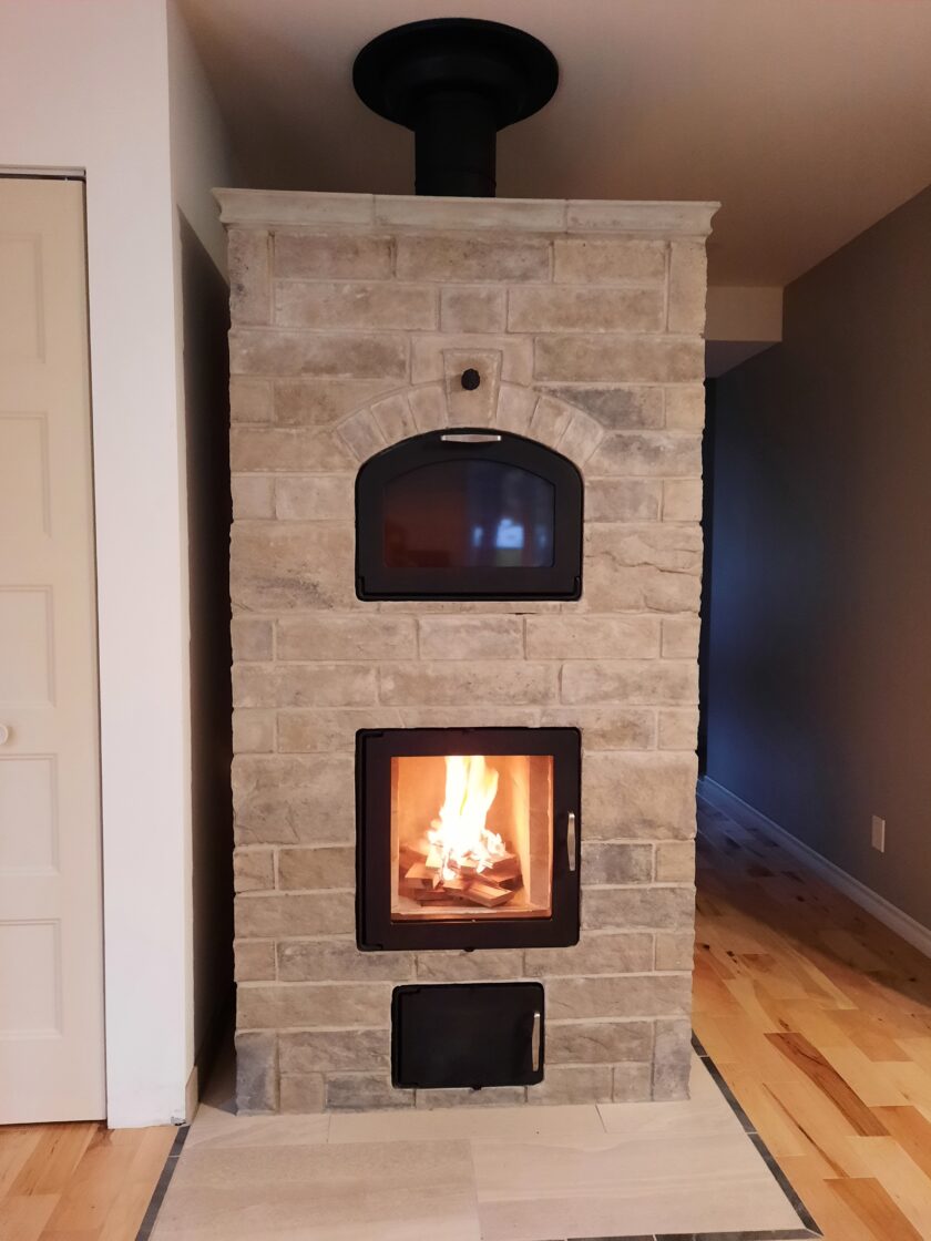
The purpose of this article is to share the specifics of one way to plumb a masonry heater to provide hot water for a home. In this project, a stainless steel heat coil in the firebox was connected to a well-insulated water tank above it which then work together through a passive thermosiphoning process to provide domestic hot water without a pump or any additional systems.
This system was installed in January of 2011 by Alan Cook of Solar Hot Water Plus and the home-owners report that it is functioning perfectly. See our portfolio entry for more on this specific Corner Heater.
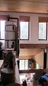
The most important thing to begin with is the relative position of the tank to the heater. The hot water tank must be above the heater and not too far away in the horizontal direction. The photo shows a good relationship between the hot water tank (which is in the upper left) and the heater (which is on the bottom right with visible stove pipe.)
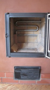
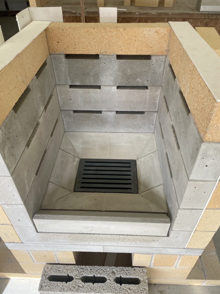
Here, you see the stainless steel hot water coil that sits in the back of the firebox. This “Hilkoil Stainless Steel Hot Water Loop” was purchased from Thermo-Bilt, Inc. out of Schenectady, NY. The coil is a variation of their 16T model, modified to accommodate the thickness of the masonry walls (simple custom drawing here). The cost for the custom coil was $275. It comes with a life-time guarantee. We cut two special bricks in the firebox to support the coil and wrapped the two parts that go through the masonry with ceramic wool to act as a firm gasket between the pipes and the masonry. We paid special attention to ensure that the pipes were placed so that they always had a slight upward slope. There is debate about where the best placement for the coil is. Many recommend burying the coil farther into the mass or placing it at the top of the heater in order not to cool down the combustion temperatures in the firebox. Because this heater was built in Northern California where winters are not so cold as elsewhere, we chose to put the coil directly in the firebox since heating hot water is one of the primary functions of the heater rather than a secondary one.
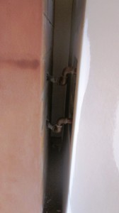
Here you can see where the coil comes out behind heater and transitions to copper plumbing. It is important to use a dielectric fitting here so that the metals do not corrode each other. Alan put these elbows in to accommodate for the fact that the wall opening turned out to be too high to go straight out. It is significant to recognize that while this upwards adjustment works out fine, the opposite – a downwards adjustment – wouldn’t work because it would go against the flow direction created in a thermosiphoning system. Put simply, you always want the colder water to be going down and the heated water to be going up.
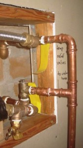
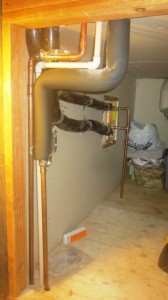
This is a detail of the plumbing just outside of the firebox which is conveniently located under the staircase. What you see are two pressure valves that are plumbed together to a drain that is below and away from the house. They are placed here to ensure that there is a safe release of pressure in the event that steam would be created in the system. Alan, the plumber, made a special point to use pressure valves and not pressure/temperature valves in this location, explaining that a “p/t” valve might release incorrectly because of the heat conducted through the metal. The upper pressure valve is just barely visible behind the upper plumbing. The little literature I have seen specifies only a pressure valve on the top/exit pipe. Alan explained that he plumbs the lower one also in the event that the plumbing might somehow get clogged inside the coil and pressure would build up backwards. A good example of how thorough and competent Alan is.
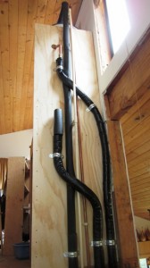
Here you can see the array of pipe going between the coil, the tank, and the domestic hot water plumbing. Alan transitioned to a flexible, pre-insulated stainless steel pipe to complete the thermosiphon loop (black-covered pipes in the background). In the foreground, you see the cold water “in” and the hot water “out” as well as the pvc drain which services the pressure/temperature valve and the pan beneath the hot water tank. Note: all pipes excluding cold water “in” should be insulated.
Here you can see the same pipes from the last photo making their way to different parts of the well-insulated water tank. Further framing will create a utility “slot” that will cover the pipes for aesthetic reasons but allow easy access for maintenance over the years.
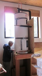
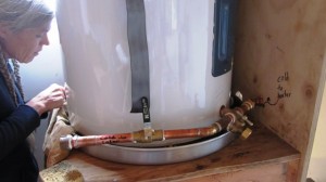
A view of Marion (homeowner) and the well-insulated 50-gallon tank.
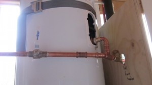
Alan removed the electrical heating element from this heater in order to plumb the hot water “in” of the thermosiphon loop. He explained that the electric element has a 1″ thread so it is necessary to reduce to 3/4″ thread to transition into the same pipe of the rest of the system. Notice that the passive solar hot water panels have also been plumbed in parallel (pipe coming from the left). The one-way “check” valve to the right of the “T” prevents any possible reverse siphoning as well as isolating the solar circuit from the wood-fired circuit.
This is the detail of the cold water “out” portion of the thermosiphon circuit. Alan has used the normal location of the drain to plumb the cold water “out” portion of the circuit for both the solar and wood-fired systems. Notice that he has maintained the functionality of the drain.
Some clarifications/additions from Al himself:
March 30, 2011
Max,
This is very good.
Small items to clarify:
At the exit point behind the stove, the barrier to differing metals (copper pipe and stainless steel coil) can be accomplished either by using a dielectric union or by using brass fittings. In this case, I used brass.
Brass is a nearly inert metal and is therefore minimally subject to decay associated with small electrical changes (e.g. electrolysis). Brass has a distinct advantage over the dielectric union which uses a rubber gasket as the barrier between steel and copper. The rubber capably insulates any electrical current that would be generated in a copper to steel setting however, the rubber will not stand up to the intense heat that is conducted from the firebox to the threads of the stainless steel stove coil. The better choice are brass fittings with both teflon tape and teflon paste to seal the threads.
Hot water is less dense than cold water and therefore floats up. This is the reason to always move heated water in an upward direction rather than risking a thermal lock seen when trying to passively move hot water in a downward direction.
The pressure relief valves near the back of the masonry heater are rated for 150 psi.
Alan
This article is offered in the spirit of encouraging the use of local fuels to meet our basic energy needs. It is important to understand that heating hot water has risks associated with it – which mainly arise when water is over-heated, turns to steam and generates a build up of pressure in the system. The techniques used here including pressure and pressure/temperature valves were implemented by a very experienced plumber. As with all things, we do not hold ourselves liable for your experiences but hope that our collective experience will contribute to wiser ways in the future. To that end, we do not currently have a live comment flow implemented but would greatly appreciate your feedback, stories, and experience to add to the article through our contact page.
Further Reading:
- Resources for Domestic Hot Water Systems for Woodstoves and Masonry Heaters
- Domestic Hot Water by Masonry Stove Builders, an excellent overview.

